3.3 Setup Private/Public Network
3.3.1 Network launch preparation
Network deployment is the installation of several nodes interacting with each other. Unlike peer-to-peer network, a DGT network can have a set structure that is thought out and configured in advance (see 2.2). The following items must be considered:
Setting up the network topology. In DGT, nodes are combined into special groups (clusters) that allow to achieve the F-BFT consensus and a significant scaling effect. Clusters can be hierarchical, allowing for the creation of additional network structures with different levels of trust. Segments are another network structure that define the access permissions to the network. Closed (private) segments require access permissions though certificates. Public segments allow free connection. Although several settings allow the network to change dynamically, its initial organization must be well thought out.
The first nodes entering the network are the so-called seed-configuration (the static core of the network) and must have a certain level of trust that allows them to recognize public keys before making changes in the topology. The initial (seed) topology of the network, including the hierarchy of clusters and segments, can be described by special configuration files (see 3.7).
DGT allows for flexible management of cryptographic libraries at the network planning stage. However, once the network is launched, the addressing in the distributed (DAG) ledger, transaction signatures, and hidden message encoding must be unified. Therefore, select the correct node assembly parameters before proceeding to launch ( see 3.7.3).
Connecting to the network and forming closed clusters requires registration and correct processing of certificates in X.509 format (binding a public key to a specific node). See 3.7.3 for details.
The payload within the network is essentially the exchange of transactions. DGT supports different families of transactions, some of which are built-in (such as #topology, handled by the topology processor; #xcert supporting certificate processing; #bgt token testing transactions - see 3.5). Network deployment assumes that all nodes within one cluster support the corresponding family of transactions.
Connection nodes to the network is carried out through a special type of transactions processed by the topology processor. Like all transactions, they can be rejected and go through a consensus mechanism.
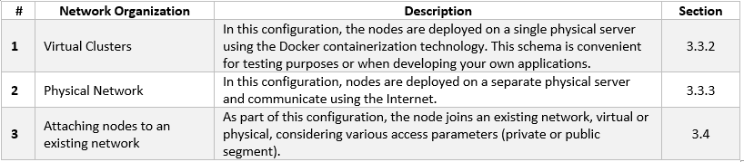
The following options for network deployment and organization of network are available:
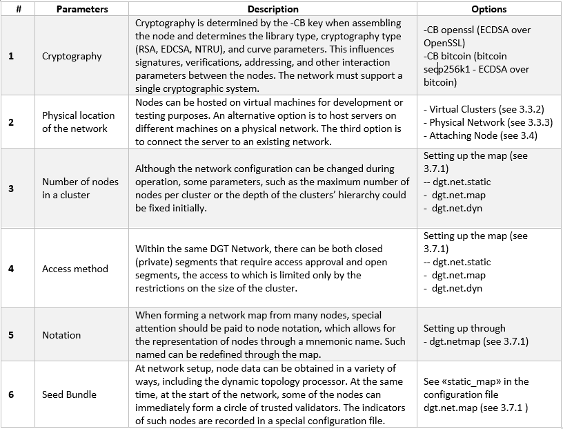
Select the network parameters prior to deployment:
3.3.2 A Virtual Cluster
3.3.2.1 Setup Virtual Nodes
Deploying a virtual cluster is the easiest way to run multiple nodes within a single virtual server (using Docker technology):
Deployment of a small network of several nodes for test purposes.
Designing your own subnet, which is expected to include nodes of different types.
Development and testing of applied solutions based on the DGT platform.
The basic steps to initializing a virtual cluster are as follows:
Prepare the server in accordance with the requirements listed in 3.1 (including setting up the operational system, Docker, Docker Compose, and the necessary instruments). Verify the correctness of the configuration (see 3.2.1.8).
Download the latest version of dgt through the “git clone” command:
git clone https://github.com/DGT-Network/DGT-MatagamiAs a result of execution, the DGT-Matagami/CORE directory is formed in the home folder of the user (HOME/DGT), from which the image of the cluster’s servers is built.
Go to the relevant folder and make sure the files are present:
cd DGT-Matagami
cd CORE
Go to the CORE/etc directory to set up settings. First, you need to edit the template for creating certificates: etc/certificate.json, by specifying the relevant parameters, including country, region, administrator e-mail and others:
nano certificate.json
Set up the topology (see 3.7.1):
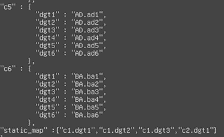
nano dgt.net.mapYou need to pay attention to the lists of nodes within each cluster, as well as the «static_map» parameter, which will define the Seed Bundle (the static core of the network [1]); see 3.7.1:
Use the «bash upDgtCluster.sh N M» command to sequentially build each of the nodes included in the Seed bundle (if necessary, install the Dashboard for a given node):
bash upDgtCluster.sh -G -SC -CB openssl NumCluster NumNodeHere:
-G - flag indicates the necessity of creating a genesis-block
-SC - flag indicates the requirement of having nodes sign transactions
-CB openssl - indicates the selectable type of cryptography (must be consistent with the network to which the node belongs). Options include openssl or bitcoin
NumCluster NumNode - cluster number and the node number in the cluster. For the first node, we set “1 1”. The mapping of the number to a notation variant using segments and clusters is reflected in the dgt.net.map file.
For example, to bring up four nodes located in two clusters, we use the following set of commands:
bash upDgtCluster.sh  -G -SC -CB openssl 1 1

bash upDgtDashboard.sh -CB openssl

bash upDgtCluster.sh -G -SC -CB openssl 1 2

bash upDgtCluster.sh -G -SC -CB openssl 1 3

bash upDgtCluster.sh  -G -SC -CB openssl 2 1
As a result of this set of commands, two clusters with four nodes will be created. To create another configuration, see 3.7.1.
3.3.2.2 Virtual Cluster Evaluation
After deploying a cluster, you need to perform the initial health check.
Using the API, we poll the available nodes [2]:
curl -v http://[SERVER_IP]:8108/peersWhere SERVER_IP is the address of the virtual machine hosting the nodes. The typical output of the command is shown in the figure below:
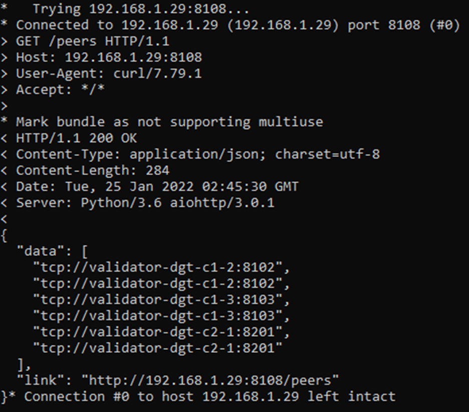
Note that the nodes have received different ports and URLs:
Let’s display the complete network topology, indicating the status of each of the nodes:
curl -v “http://[SERVER_IP]:8108/topologyA typical output contains a complete network map, for which the active nodes receive the «node_state: active» status, as well as an indication of the corresponding roles: plink, leader, etc.

Verifying the interaction via console
Each of the running nodes has its own console. This allows for the testing of a scenario where one of the nodes executes commands and then the results are checked through another node.
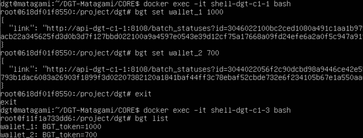
Log in to the console of the first node and create some bgt wallets. Then exit the console:
docker exec -it shell-dgt-c1-1 bash
bgt set wallet_1 1000
bgt set wallet_2 700
exit
Through the console of another node, we display a list of wallets:
docker exec -it shell-dgt-c1-3 bash
bgt list
The output should confirm data synchronization between nodes. The output contains commands that display a list of wallets created through the console of another node.
Checking node status via Dashboard
If the Dashboard component is installed, checking the status of the nodes can be performed using the browser of the client computer:
http://[SERVER_IP]:8003/ -> Nodes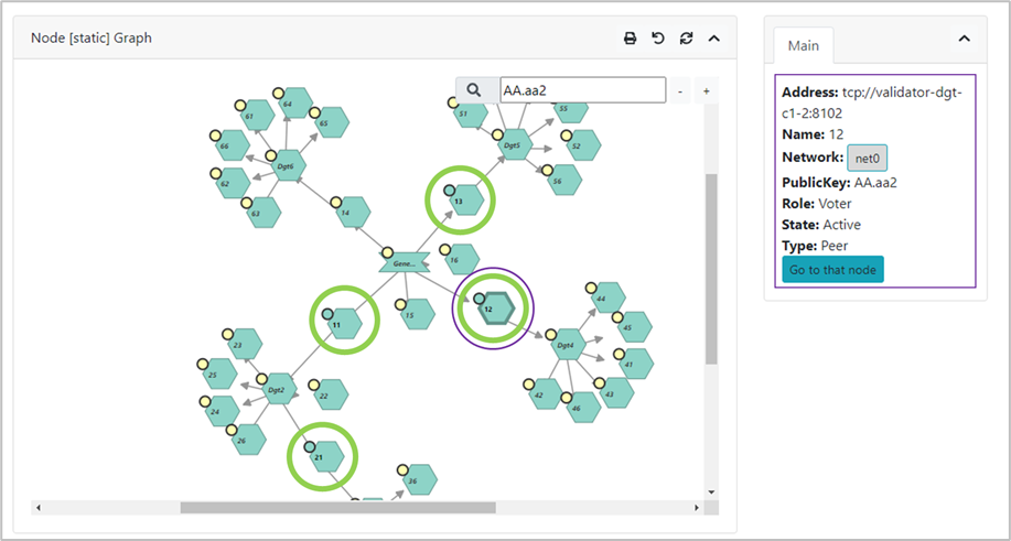
Querying the API of each of the nodes allows for finer testing of transaction execution.
By default, each of the nodes is associated with its own API service that executes the appropriate commands (endpoints, see 4.1). If a virtual cluster is launched, the corresponding IP servers have the same [SERVER_IP], however, they use different ports, the correspondence of which to a given node is determined by the «upDgtCluster.sh» [4] file, see also 3.2.4. The default ports ([API] parameter) are as follows:
Cluster 1 Node 1: 8108
Cluster 1 Node 2: 8109
Cluster 1 Node 3: 8110
Cluster 2 Node 1: 8208
To check using the API, execute the command to display a list of wallets for the first node, change the amount on the first one by using the “inc” increasing command, then check the balance through an API of another node. We call the API from the client system using the curl utility.
We display the status of wallets on the first node and make an increase (we use the previously created test wallets wallet_1 and wallet_2; if they are not available, you must also execute the commands to create them (see 4.1.9.2):
curl "[SERVER_IP]:8108/run?family=bgt&url=tcp%3A%2F%2Fvalidator-dgt-c1-1%3A8101&cmd=list"
curl "[SERVER_IP]:8108/run?family=bgt&url=tcp%3A%2F%2Fvalidator-dgt-c1-1%3A8101&cmd=inc&wallet=wallet_1&amount=100"
We check the received amount through another node:
curl "[SERVER_IP]:8208/run?family=bgt&url=tcp%3A%2F%2Fvalidator-dgt-c2-1%3A8201&cmd=list"
Expected result: even though the command was sent to the node in the second cluster, the data is synchronized, and the correct amount was displayed for the first wallet.
3.3.3 A Physical Network
3.3.3.1 Network Deployment Preparation
It is typical to deploy a virtual network (see 3.3.2) for solving experimental problems or developing applications. Operating the network in enterprise environments may require the formation of nodes on physically distinct servers. Servers may also be located on different physical networks protected by a firewall. The installation is generally similar to deploying a virtual network (see 3.3.2`_) with the following amendments:
When assembling nodes located on physically different servers, additional parameters are used for the bash command, depending on whether the node is connected to closed segments (private network) or public segments - see below.
When servers are behind firewalls, network-supporting ports must be opened ([NET] parameter in the «upDgtCluster.sh» file, see 3.2.4).
In case of deploying nodes in the internal network, you must use an explicit indication of the node’s IP (flag -H 7, host - see below). [5]
Network deployment must be preceded by the design of its topology, including planning for the size of clusters and segments (see 3.7.1).
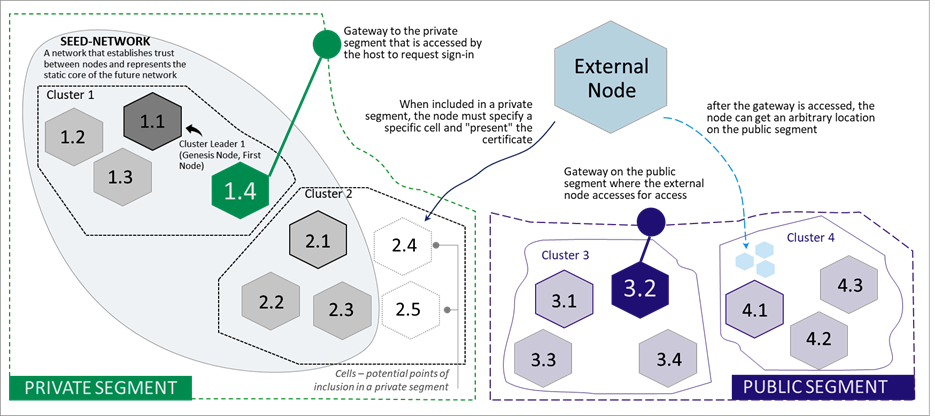
The initial implementation of the network, also called the “static core” or “seed network” is a group of nodes / clusters that form special trust relationships (public keys of such nodes are known in advance and are registered at the time of kernel deployment). The joining of other nodes requires the processing of node certificates for private segments and / or dynamic joining in the case of public segments.
A node attached to a seed-network is called an external node. To establish interaction with the network, an entry point must be defined - a gateway, a node of the source network through which a new node is connected. Connecting to private (closed) and public segments is different [6]
in case of a private segment, the attaching node has a concrete entry point (cluster number and cell number, as well as a verifiable and valid certificate that assigns a public key to the node)
in case of a public segment, the dynamic topology is used (the certificate is accepted, but verified, while joining is conducted through any available point, subject to the restrictions of the cluster).
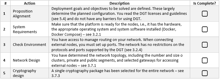
Each network node is a server that simultaneously acts as a client of the rest of the network that gains access through other nodes (gateways). To prepare for correct network deployment, it is suggested that you perform the following self-check:
3.3.3.2 Setup a physical network
Network deployment is determined by the selected configuration options (including topology, network environment, and cryptography). The following basic steps allow you to deploy a physical network:
Carefully check that the prerequisites are met (see 3.3.3.1).
Deploy the Seed Network (static network core) by performing the following procedures (the initial network can be completely virtual - see 3.3.2):
Prepare the hardware platform and system software (one of more physical servers that meet the requirements for platform nodes - see 3.2.1).
Prepare the necessary topology configuration of the seed network (see 3.7.1).
Sequentially expand the seed network nodes using the command:
bash upDgtCluster.sh  -G -SC -H [SERVER_IP] -CB openssl
   -S [GATE_URL:GATE_PORT] NumCluster NumNode
Here:
-G - a requirement to create or synchronize DAG starting from the genesis block.
-SC - a flag indicating the need for transactions to be signed by nodes.
-H [SERVER_IP] - host, IP address of the physical server on which the node is running. This is important for launching a network in the internal network; in case of absence, it will be determined as an address in the Internet and nodes will need to be launched even if the network is internal
-CB openssl/bitcoin - a flag that indicates the selected cryptography; cryptography must be the same for the entire network.
-S [GATE_URL:GATE_PORT] - a pointer to the gateway through which each subsequent node is connected (except or the first one, moreover this is unnecessary in case of deploying a virtual cluster, see 3.3.2.1)
NumCluster - the number of the cluster to which the current node is joining (“1” is recommended for the first node)
NumNode - the number of the node joining (“1” is recommended for the first node)
Launching the Dashboard [7] component (optional) with the command:
bash upDgtDashboard.sh -CB openssl
Launching the system monitoring subsystem (if necessary) - see 3.8.3.
Check the correctness of seed-network deployment using procedures similar to the virtual cluster checks (see 3.3.2.2): BGT transaction check, API check, Dashboard check (if it is running).
Connect external nodes to the seed network:
If nodes are included into closed (private) segments defined by topology (see 3.7.1), then for each such node execute the following command in sequence (such nodes must have agreed-upon certificates and their place in the network (a cell determined by the topology configuration)):
bash upDgtCluster.sh -G -E -SC -CB openssl -P [NODE_PORT] -H [SERVER_IP] -N [NETWORK_NAME] -S [GATE_URL:GATE_PORT] NumCluster NumNode
Here:
-G - a requirement to create or synchronize DAG, starting from the genesis block.
-E - flag indicating that the connected node is external
-SC - flag indicating the need for transactions to be signed by nodes
-P [NODE_PORT] - flag that defines the port opened on a remote node, through which a given node communicates with the network.
-H [SERVER_IP] - host, IP address of the physical server on which a node is running. It is important for starting a network on an internal network; in its absence, it will be defined as an address on the Internet and nodes will need to be opened even if the network is internal.
-CB openssl/bitcoin - flag indicated the selected cryptography; cryptography must be the same for the entire network.
-S [GATE_URL:GATE_PORT] - a pointer to the gateway through which each subsequent node is connected (except for the first one; it is also not necessary in case of deploying a virtual cluster, see 3.3.2.1)
NumCluster - the number of the cluster to which the current node is connecting (“1” recommended for the first node)
NumNode - the number of a node that is connecting (“1” is recommended for the first node)
In case of connecting external nodes to a public segment, use the following command:
bash upDgtCluster.sh -G -E -P [NODE_PORT] -N my_host_net -S [GATE_URL:GATE_PORT] dyn 1Here:
dyn 1 - a pointer to the dynamic topology and cluster to which the node wants to connect.
-S [GATE_URL:GATE_PORT] - you can state the gateway as a link to a file (an anchor file in JSON format) hosted in the cloud (for example, Google Drive). For example:
https://drive.google.com/file/d/1o6SEUvogow432pIKQEL8-EEzNBinzW9R/view?usp=sharingThe anchor file has the following structure, which contains a directory of available gateways to public networks (can also use special services that provide dynamic SD-WAN configuration):
{
 "public":["tcp://validator-dgt-c1-1:8101","tcp://209.124.84.6:8101"],
 "private": [],
 "restapi": ["http://dgt-api:8108"]
}
After connecting external nodes, carry out the checks like 3.3.2.2.
3.3.3.3 DGT Network Example
This section provides an example physical network configuration with the following settings:
The network unites 6 nodes, from which three clusters are formed: cluster 1 (nodes c1-1, c1-2, c1-3), cluster 2 (nodes c2-1, c2-2) and cluster 3 (sole node c3-1);
Static core (seed network) that is represented by a virtual cluster of nodes c1-1, c1-2, c1-3, c2-1 [8] located on one physical server Dell Server-1 with the IP [9] = 192.168.1.134 (thus the initial network is represented by two clusters).
Node c2-2 is located on a separate physical server, AMD Server-2 with IP = 192.168.1.16 and “completes” cluster 2 in the private seed-network segment.
Nodes c2-3 and c3-1 are located on a separate physical server, as well as in a virtual cluster and are placed in clusters 2 and 3, respectively.
Node c1-1 acts at the only gateway for connecting external nodes to the seed-network. Services and network (NET) ports are set automatically according to upDgtCluster.sh
The nature of the testnet is presented below in principle:

The network is deployed as follows:
Installation of a virtual cluster (c1-1, c1-2, c1-3, c2-1) representing the seed-network is done in the CLI Dell-Server-1:
bash upDgtCluster.sh  -G -SC -H 192.168.1.134 -CB openssl 1 1
bash upDgtCluster.sh  -G -SC -H 192.168.1.134 -CB openssl 1 2
bash upDgtCluster.sh  -G -SC -H 192.168.1.134 -CB openssl 1 3
bash upDgtCluster.sh  -G -SC -H 192.168.1.134 -CB openssl 2 1
The installation of the c2-2 node (external node in a private segment) is set up as follows:
bash upDgtCluster.sh -G -E -SC -CB openssl -P 8202 -H 192.168.1.16 -N net2022 -S tcp://192.168.1.134:8101 2 2You should pay attention to the parameters:
-P 8202 - of the c2-2 node, through which communication with the network is maintained.
-N net2022 - network name (domain name) must be the same for all nodes of this physical network.
-H 192.168.1.16 - IP of the physical server (AMD Server-2) on which the node c2-2 is installed.
-S tcp://192.168.1.134:8101 - pointer to the gateway to the network (which is node 1)
2 2 - cluster number and node number
Deploying nodes c2-3 и c3-1 [10] in the CLI servers AMD Server-3:
bash upDgtCluster.sh -G -E -SC -CB openssl -P 8203 -H 192.168.1.126 -N net2022 -S tcp://192.168.1.134:8101 2 3
bash upDgtCluster.sh -G -E -SC -CB openssl -P 8301 -H 192.168.1.126 -N net2022 -S tcp://192.168.1.134:8101 3 1
Footnotes